CONNECTOR
CONECTOR
5
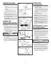
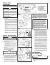
SOCKET
ENCHUFE
LIGHT LENS
LAMPARA
FILTER RETAINER
SOPORTE DEL FILTRO
TABS
APENDICES
FAN ASSEMBLY
Remove filter. Remove two screws holding motor
bracket to range hood, and unplug fan assembly. Be
careful not to allow fan assembly to drop when screws
are removed. (FIG. 14)
CLEANING
Clean your hood with a mild detergent suitable for
painted surfaces. DO NOT USE ABRASIVE CLOTH,
STEEL WOOL PADS OR SCOURING POWDERS.
Fan assembly may be vacuumed. Fan assembly is
permanently lubricated, and never needs oiling.
HOW TO AVOID A COMMON RANGE-TOP
GREASE FIRE
• Your range hood provides a protective barrier
between the cooking surface and the cabinets.
• Keep fan, filters and grease laden surfaces
CLEAN according to instructions.
• Always turn hood ON when cooking at high heat
to keep the cooking area and the hood cooler.
• Use high heat settings only when necessary.
• Never leave cooking surface unattended. Boil-
over causes smoking and greasy spillovers that
may ignite.
• Always use adequate-sized utensils.
• If preparing flaming foods, such as Cherries Ju-
bilee, always turn hood ON to HIGH to prevent
a high heat situation which can cause damage
or fire.
HOW TO EXTINGUISH A COMMON RANGE-
TOP GREASE FIRE
• Never pick up a flaming pan. If dropped, flames
can spread quickly.
• DO NOT USE WATER! A violent steam explo-
sion may result. Wet dishcloths or towels are
also dangerous.
• Smother flames with a close fitting lid, cookie
sheet or metal tray.
• Flaming grease can also be extinguished with
baking soda or a multi-purpose dry chemical
extinguisher.
• Turn off surface units - if you can do so without
getting burned.
FIG. 10
FIG. 11
FIG. 12
FIG. 13
FILTER
FILTRO
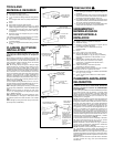
BLACK WIRES
CABLES NEGROS
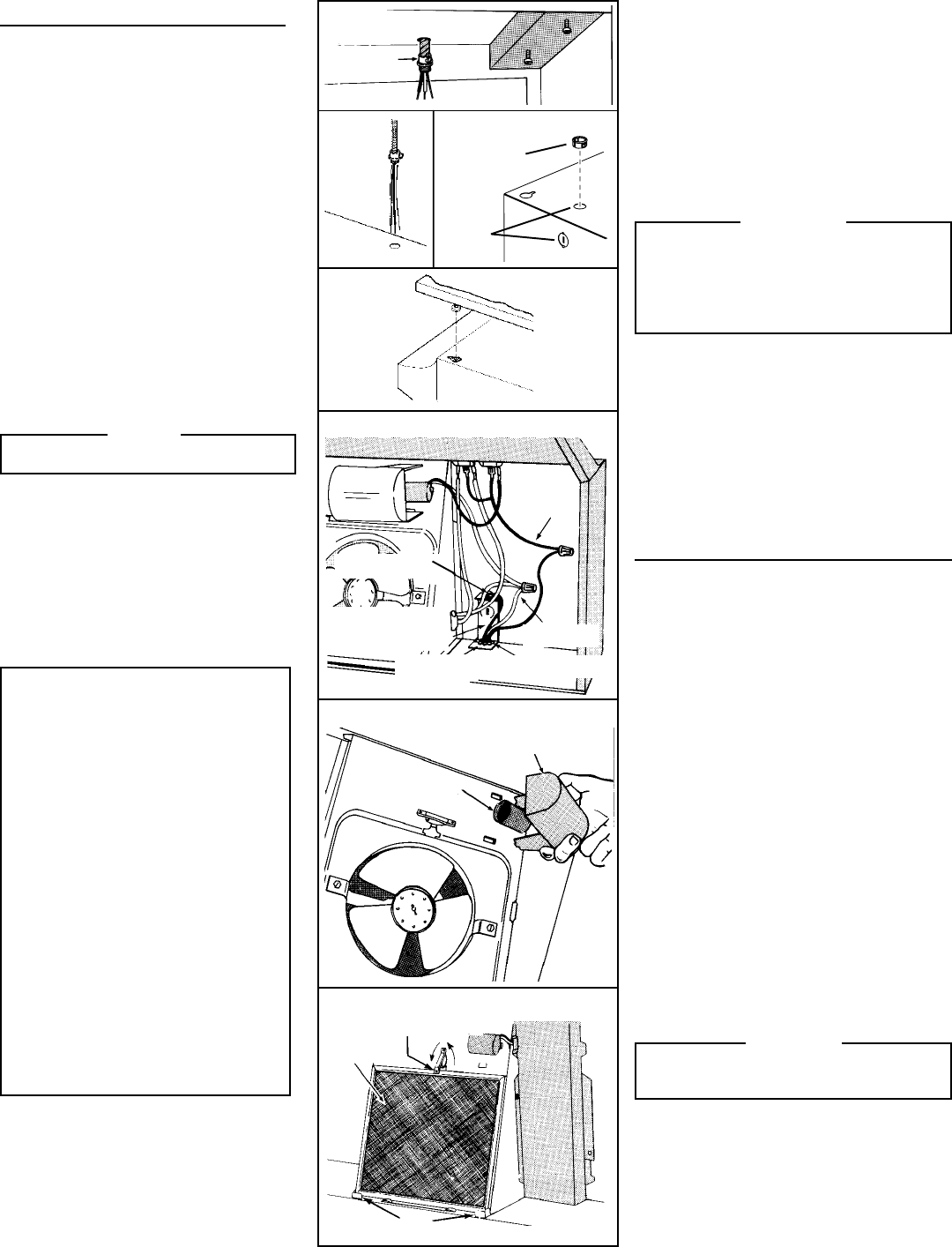
2. Coloque el extractor para que:
a.) El cableado salga por la salida del tapón. (FIG .10)
(Serie MX solamente: Utilice el ojal reforzado
provisto en bolso de las piezas.)
b.) Las partes grandes de las ranuras se ajustan en
los tornillos de la montura del extractor. (FIG. 10)
c.) El conector del ducto/regulador se deslice dentro
del ducto. (SOLAMENTE para extractores 40000,
42000 y 42000D)
3. Ajuste el extractor para que la parte del frente se nivele
con el gabinete.
4. Ajuste los tornillos de la montura del extractor con
firmeza.
5. Ajuste el cableado al extractor con el conector eléctrico
adecuado para el tipo de cable que se va a utilizar.
GREEN GROUND SCREW
TORNILLO DE TIERRA VERDE
GROUND WIRE (BARE OR
GREEN WIRE)
CABLE DE TIERRA (CABLE
DESCUBIERTO O VERDE)
GROUNDING BRACKET
MENSULAS DE TIERRA
STAR LOCKNUT
TUERCA DE FIJACION
DE ESTRELLA
WHITE WIRES
CABLES BLANCOS
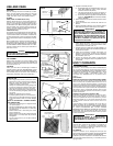
USE AND CARE
SWITCHES
The fan and light are each controlled by a rocker
switch. The light switch has two positions, “ON” and
“OFF”. The fan switch has three positions - “HIGH”,
“LOW” and “OFF”. ( “OFF” is the middle position.)
FILTERS
40000, 42000 & 42000D Hoods Only:
Remove aluminum filter by turning filter retainer to
one side. (FIG. 13) Filter should be washed once a
month in a hot detergent solution. Aluminum filters
are dishwasher safe. When installing filter, make sure
that filter slides under retaining tabs on back of fan
housing. Turn filter retainer so that arrows on retainer
point toward front and back of hood.
41000 Hoods Only:
The 41000 hood is equipped with a ductfree filter. Re-
move filter by turning filter retainer to one side. (FIG.
13) The ductfree filter is not washable, and will last up
to twelve months with normal use. Replace the filter
when colored side becomes noticeably dirty or discol-
ored.
When installing filter, make sure that filter slides un-
der retaining tabs on back of fan housing. MAKE
SURE THAT COLORED SIDE OF FILTER IS NEXT
TO FAN WHEN FILTER IS INSTALLED. Turn filter
retainer so that arrows on retainer point toward front
and back of hood.
WARNING
ALWAYS DISCONNECT ELECTRIC POWER BE-
FORE SERVICING RANGE HOOD.
ADVERTENCIA
TODAS LAS CONEXIONES ELECTRICAS DEBEN SER
REALIZADAS DE ACUERDO CON LOS CODI-GOS LO-
CALES, REGLAMENTOS Y CODIGOS ELECTRICOS
NACIONALES. SI NO ESTA FAMILIAIZADO CON LOS
METODOS DE INSTALACION DE CABLEADO
ELECTRICO, CONTRATE LOS SERVICIOS DE UN
ELECTRICISTA CALIFICADO.
6. Pele 1/2 plg. de aislante de los cables. Conecte los
cables, blanco con blanco, negro con negro y el verde
con el orificio hecho con el tornillo de tierra verde,
proporcionado en la bolsa. (FIG. 11)
7. Coloque de nuevo la tapa de la caja del cableado y el
tornillo. Asegúrese de que todo el cableado quede bien
contenido en el interior.
8. Instale el foco (máximo 75 watts). Para lograr una
instalación más sencilla, presione los protectores
plásticos y retírelos del extractor. Recuerde reinstalar
los protectores. (FIG. 12)
9. Conecte la corriente para revisar la operación del
abanico y la luz. Asegúrese de que el regulador funcione
con libertad.
USO Y CUIDADOS
LOS INTERRUPTORES
El abanico y el foco están controlados individualmente
por un interruptor balancín. El interruptor del foco tiene
dos posiciones, ENCENDIDO (“ON”) y APAGADO (“OFF”).
El interruptor del abanico tiene tres posiciones - ALTA
(“HIGH”), BAJA (“LOW”) y APAGADO (“OFF”). (El
interruptor para APAGADO está en la posición de en
medio.)
LOS FILTROS
Solamente los extractores modelo 40000, 42000 y 42000D:
Retire el filtro de aluminio girando el contenedor del filtro
hacia un lado. (FIG. 13) El filtro debe lavarse una vez al
mes en una solución jabonosa caliente. Los filtros de
aluminio se pueden lavar en la lavadora de platos. Cuando
instale un filtro, asegúrese de que el filtro se deslice debajo
de los apéndices en la parte trasera del compartimiento
del abanico. Gire el contenedor del filtro para que las
flechas del contenedor apunten hacia el frente y la parte
trasera del extractor.
Solamente los extractores modelo 41000:
El extractor 41000 está equipado con un filtro sin ducto.
Retire el filtro girando el contenedor del filtro hacia un
lado. (FIG. 13) El filtro sin ducto no se puede lavar, y durará
hasta doce meses con un uso normal. Coloque de nuevo
el filtro cuando el lado de color se torne sucio o se
decolore.
Cuando instale un filtro, asegúrese de que el filtro se
deslice por debajo de los apéndices en la parte trasera
del compartimiento del abanico. ASEGURESE DE QUE
EL LADO COLOREADO DEL FILTRO QUEDE
ENSEGUIDA DEL ABANICO, CUANDO EL FILTRO SEA
INSTALADO. Gire el contenedor del filtro para que las
flechas de el contenedor apunten hacia el frente y la parte
trasera del extractor.
ADVERTENCIA
DESCONECTE SIEMPRE EL CABLE DE ELEC-
TRICIDAD ANTES DE DARLE SERVICIO DE
MANTENIMIENTO AL EXTRACTOR.
EL ENSAMBLE DEL ABANICO
Retire el filtro. Retire los dos tornillos que sostienen el
motor en el extractor, y desconecte el ensamble del
abanico. Asegúrese de no permitir que el abanico se caiga
cuando retire los tornillos. (FIG. 14)
LA LIMPIEZA
Limpie su extractor con un detergente suave que sea
adecuado para superficies pintadas. NO UTILICE PIEZAS
DE TELA ABRASIVAS, FIBRAS O DETERGENTE.
El abanico puede ser aspirado. El ensamble del abanico
está lubricado permanentamente y no necesita que se le
agregue aceite.
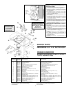
MX Series Only
FIG. 9
GROMMET
OJAL REFORZADO
ELECTRICAL
KNOCKOUTS
TAPÓNES
ELÉCTRICOS


